Modifying Antminer Control Board EEPROM to Run Official BeagleBone Images
I recently picked up a few ARM Cortex A8 boards, which appear to be retired Antminer control boards. These boards are modified versions of the open-source BeagleBone Black board, with basically the same PCB layout but with some components removed.
Board Appearance
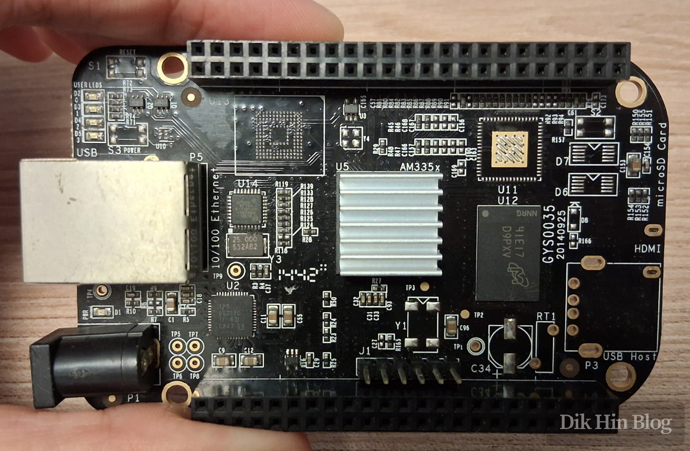
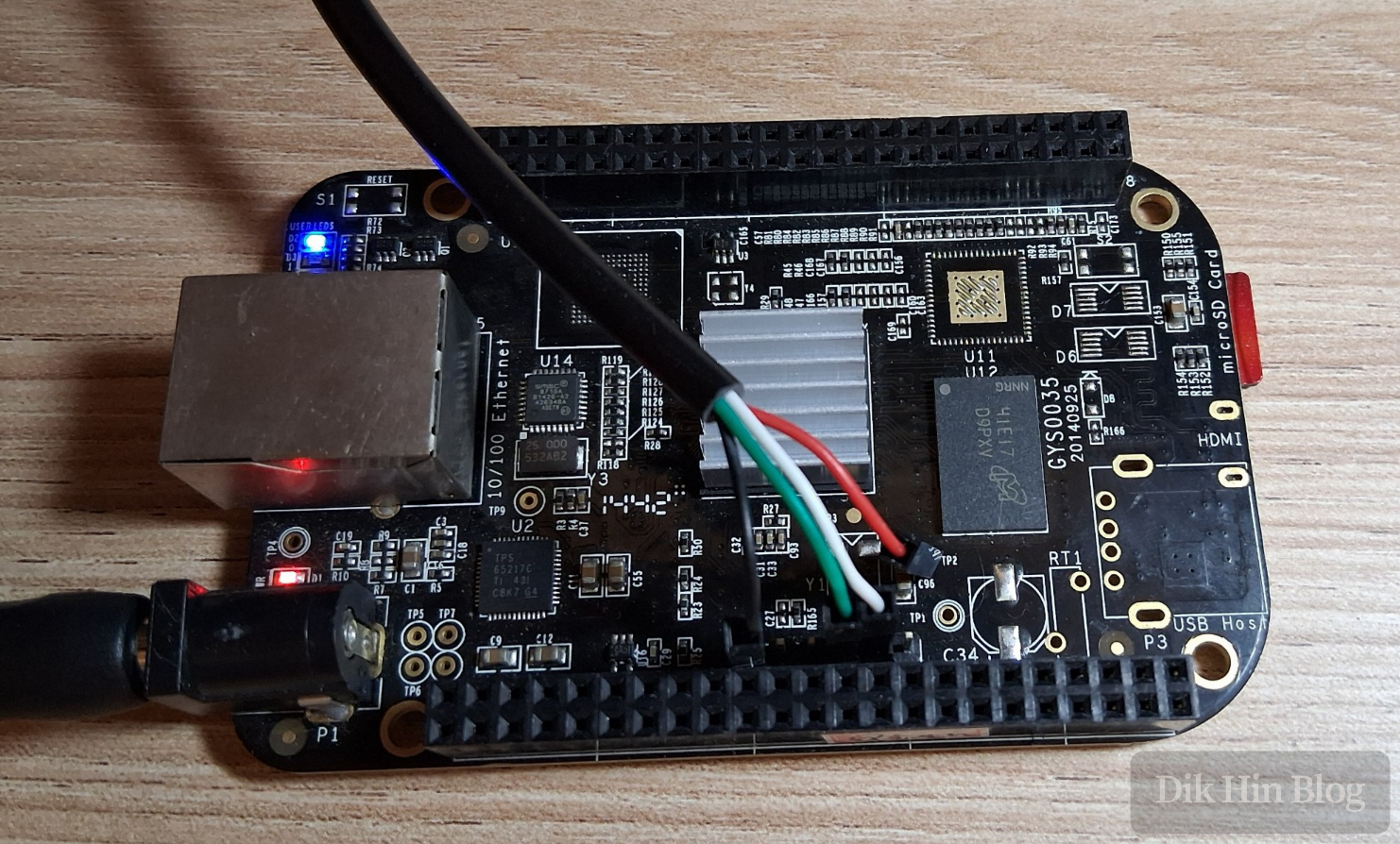
Here’s what the board looks like. Judging by the solder joints, the DC jack and UART pin header were hand-soldered later. I added the heatsink myself, though this processor doesn’t generate much heat and doesn’t really need it - passive cooling through the PCB is sufficient. I just think it looks better with a heatsink.
Comparison with Official Board
The differences between the Antminer control board and the official BeagleBone Black board are as follows:
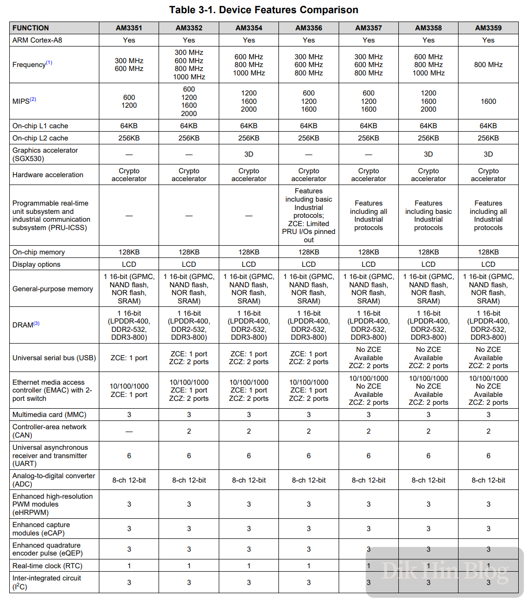
- The official version uses TI’s AM3358 processor, while the control board uses AM3352. They belong to the same processor family (AM335x Sitara™ Processors). The difference between these two processors is minimal - both are single-core 32-bit Cortex A8 running at 1GHz. The main difference is that AM3352 lacks 3D graphics acceleration, but this doesn’t affect headless use cases.
- Both the official version and the control board have 512MB DDR3L memory using Micron chips
- The official version has onboard 4GB eMMC, which is removed on the control board
- The control board removed the Micro HDMI output jack and related circuitry
- The control board removed the USB Host and USB Client jacks and related circuitry
- All tactile buttons on the control board were removed: power, reset, and boot source selection
Power-On Test
I downloaded an official image from Beaglebone and flashed it to a Micro SD card using Rufus to see if it would boot. The UART serial port voltage is 3.3V TTL, so I found a matching USB-to-serial adapter, connected GND, TX, and RX to the board, plugged it into the computer, and set the baud rate to 115200.
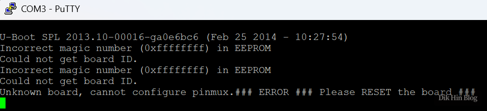
After powering on with a 5V DC supply, the LED lit up but there was no output at all. I tried flashing several different systems until an older system finally gave a meaningful error message: Incorrect magic number (0xffffffff) in EEPROM
EEPROM Problem Analysis
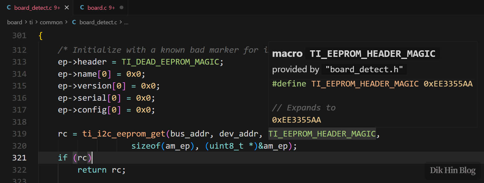
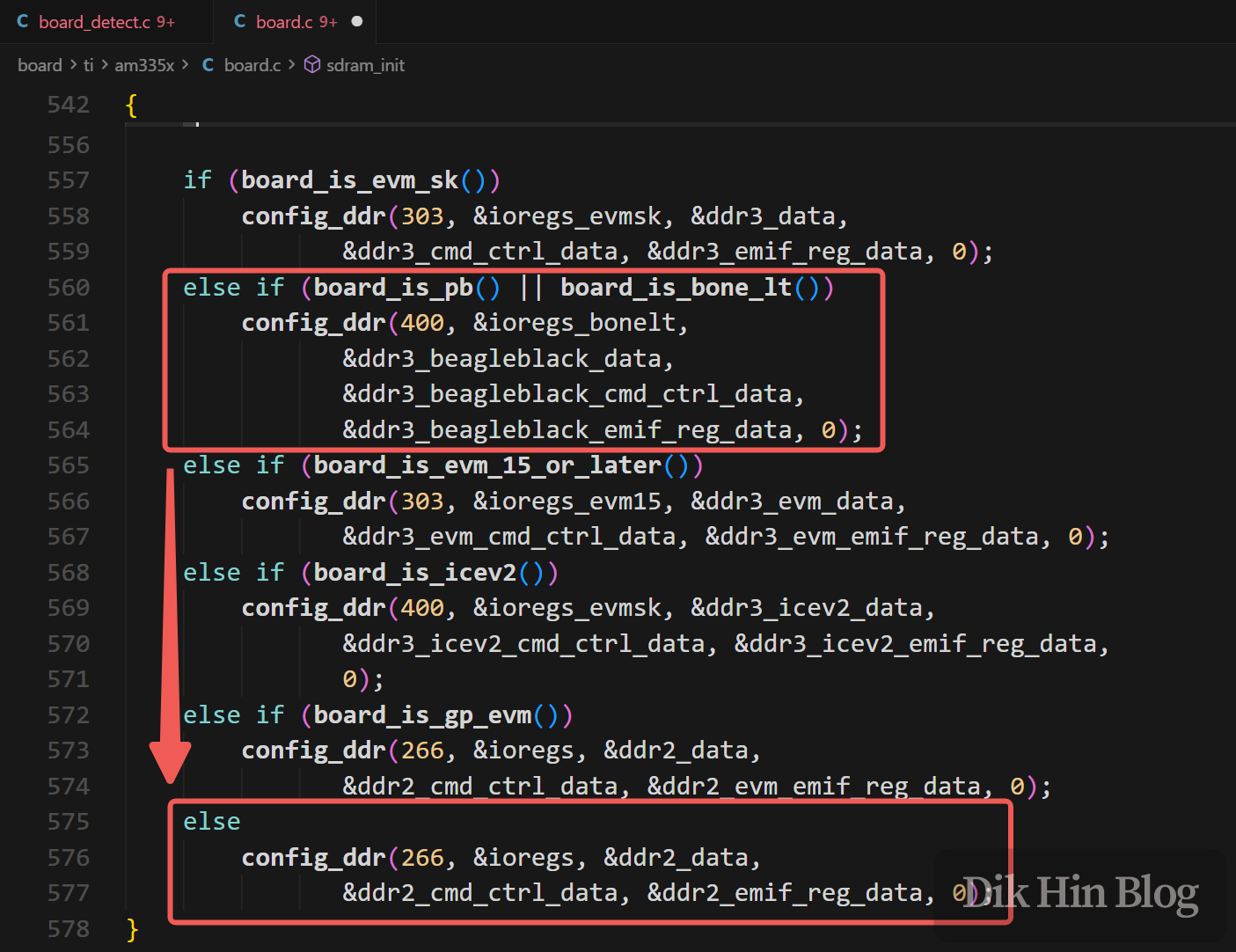
After reading the official BeagleBone documentation and gathering information online, I discovered there’s a 4KB EEPROM on the board, and the u-boot in the image validates the EEPROM information during boot. Reading the latest u-boot source code, I found related code showing that if the EEPROM information is incorrect, u-boot can’t determine the board model and will initialize the memory chip as the default DDR2-266MHz instead of the DDR3-400MHz on the BeagleBone Black (Double Data Rate, so the data transfer rate is 800MHz, matching the official documentation). With incorrect protocol and timing, the board can’t run, which is probably why there was no output after power-on.
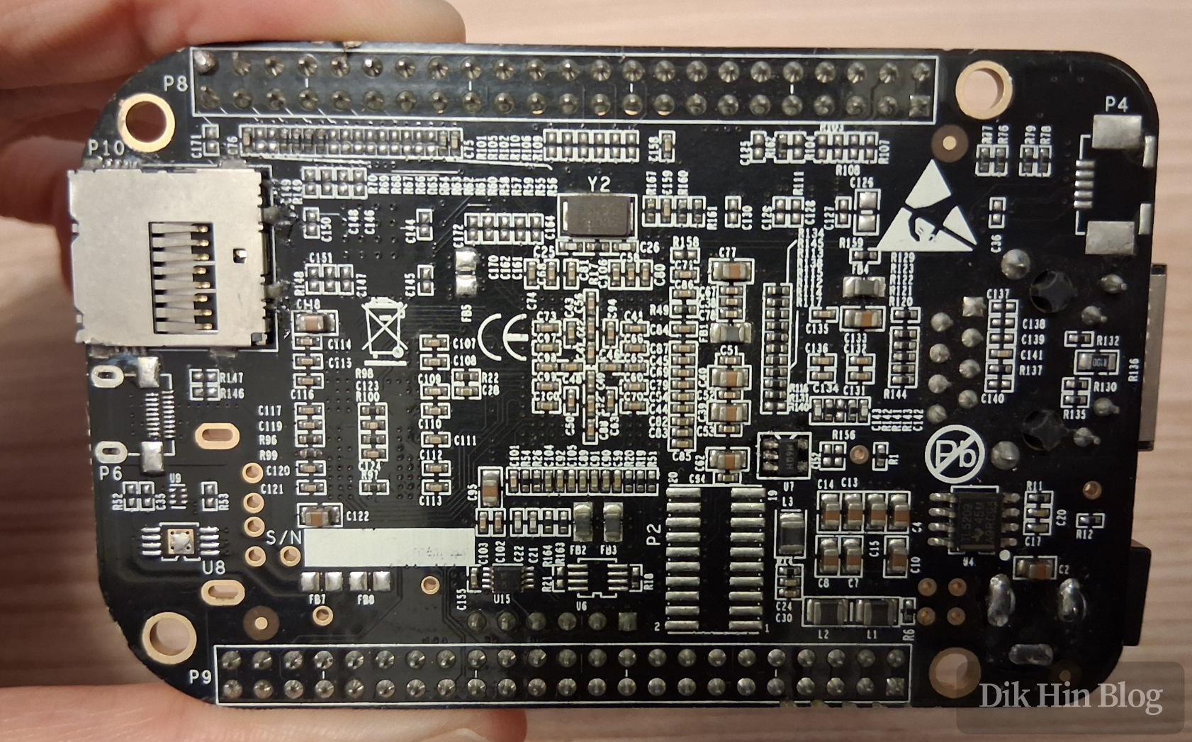
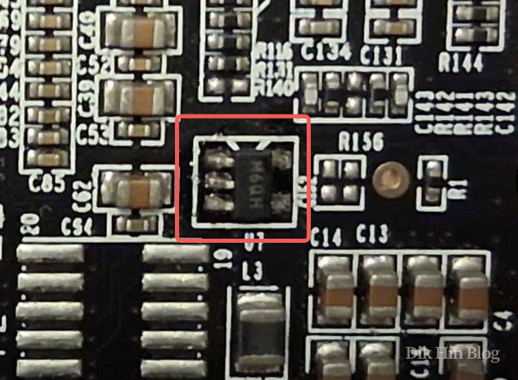
The EEPROM chip on the board is Microchip’s 24LC32AT-I/OT in a SOT-23-5pin package. Judging by the solder joints, this chip was also hand-soldered later. It seems the control board system itself doesn’t need EEPROM, but the seller added one at the U7 position on the back of the board to facilitate running official images later:
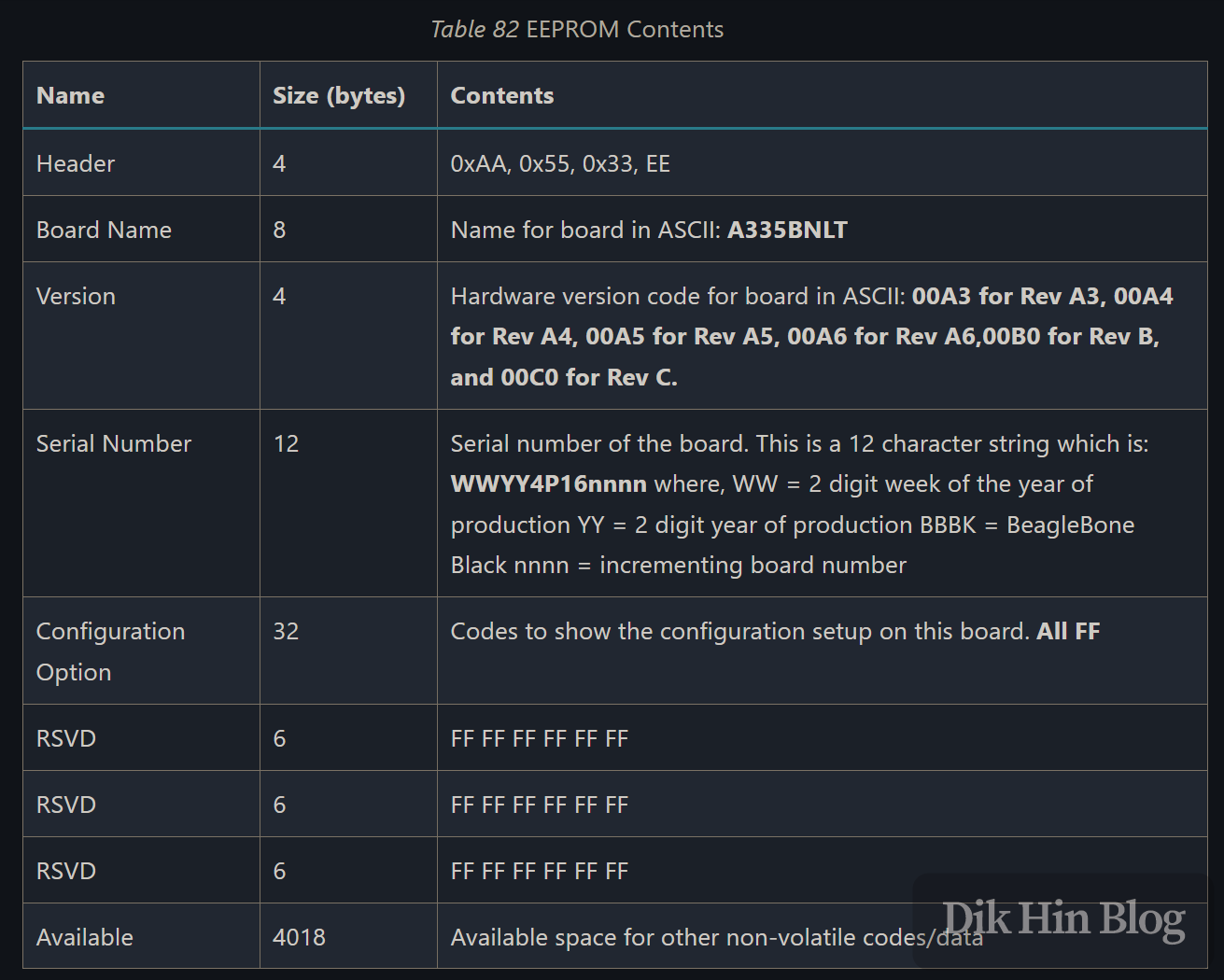
Since the newly soldered EEPROM data is empty, according to the official documentation, the EEPROM data needs to be populated. The format is as follows:
Writing EEPROM Data
I found a third-party image online that can boot the board into the u-boot console without EEPROM validation. After flashing it and powering on, I successfully entered the console.
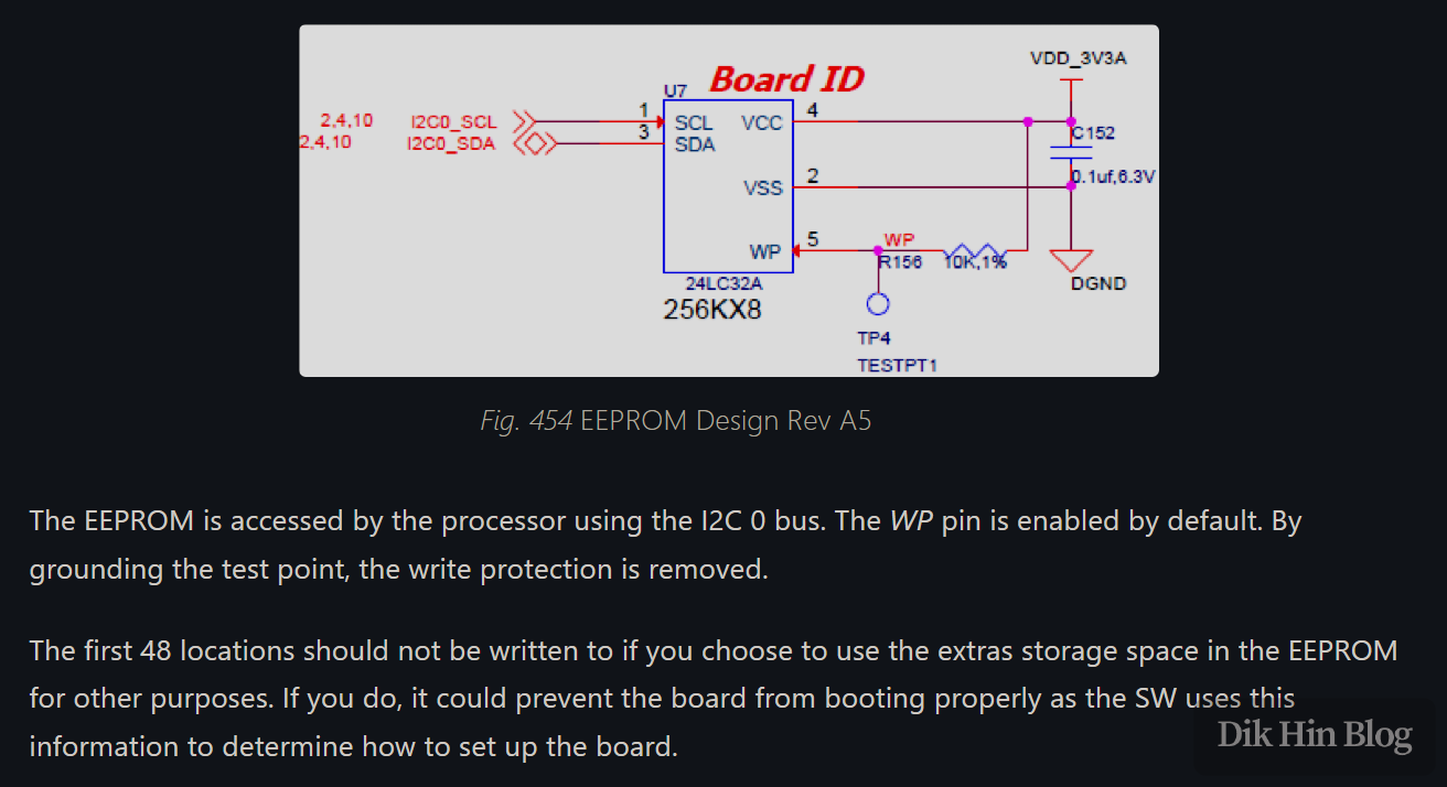
According to official documentation, the EEPROM is on I2C bus 0. For the address, we need to check the circuit design. However, according to the 24LC32A datasheet, the SOT-23 5-pin package doesn’t provide A0-A2 pins for address selection, so they’re treated as 000. Therefore, the device address is fixed at 1010000, which is 0x50 in hexadecimal, so we need to operate the EEPROM at address 0x50 on bus 0.
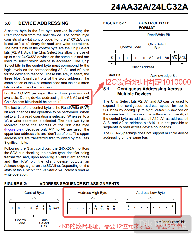
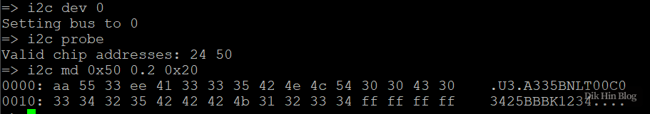
In the u-boot console, I selected i2c bus 0, then probed it and saw that address 0x50 was valid as expected. Then I started using i2c mw to write data according to the official EEPROM data format. For the serial number, I used the current week number and 1234. Note that since the data address requires 2 bytes, we need to add .2 to the address parameter; without it, the default is .1 (=1 byte).
i2c dev 0
i2c probe

# 0xAA5533EE
i2c mw 0x50 0x00.2 0xAA
i2c mw 0x50 0x01.2 0x55
i2c mw 0x50 0x02.2 0x33
i2c mw 0x50 0x03.2 0xEE

# A335BNLT
i2c mw 0x50 0x04.2 0x41
i2c mw 0x50 0x05.2 0x33
i2c mw 0x50 0x06.2 0x33
i2c mw 0x50 0x07.2 0x35
i2c mw 0x50 0x08.2 0x42
i2c mw 0x50 0x09.2 0x4E
i2c mw 0x50 0x0A.2 0x4C
i2c mw 0x50 0x0B.2 0x54

# 00C0
i2c mw 0x50 0x0C.2 0x30
i2c mw 0x50 0x0D.2 0x30
i2c mw 0x50 0x0E.2 0x43
i2c mw 0x50 0x0F.2 0x30

# 3425BBBK1234
i2c mw 0x50 0x10.2 0x33
i2c mw 0x50 0x11.2 0x34
i2c mw 0x50 0x12.2 0x32
i2c mw 0x50 0x13.2 0x35
i2c mw 0x50 0x14.2 0x42
i2c mw 0x50 0x15.2 0x42
i2c mw 0x50 0x16.2 0x42
i2c mw 0x50 0x17.2 0x4B
i2c mw 0x50 0x18.2 0x31
i2c mw 0x50 0x19.2 0x32
i2c mw 0x50 0x1A.2 0x33
i2c mw 0x50 0x1B.2 0x34
After writing, I read it back to verify - it worked!
Successfully Booting Official Image
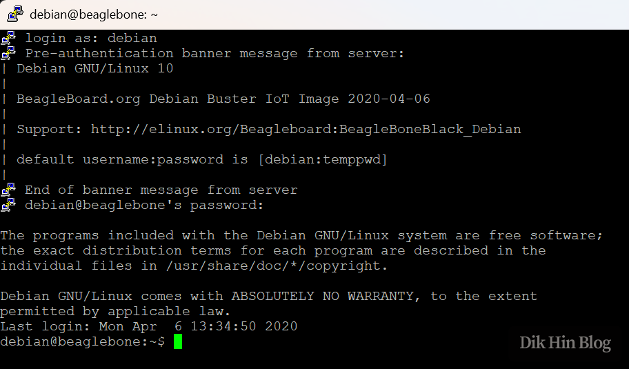
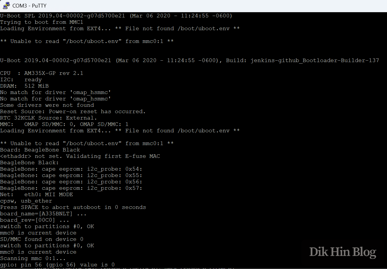
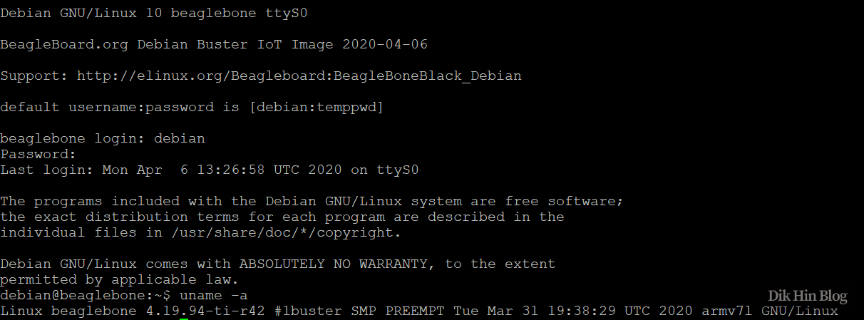
I re-flashed the official image, using the Debian 10.3 version from 2020-04-06, and it booted successfully. Newer versions don’t work - the kernel won’t run after u-boot hands off, getting stuck at “Starting kernel …” or throwing exceptions during kernel boot. I’ll investigate the reason later. From the u-boot log, I can see it now correctly identifies the board model:
Expanding System Partition
The default system account is debian with password temppwd. After entering the system, I checked the kernel version with uname - it’s 4.19.94. Also, the image is only 4GB, so I needed to manually expand it to use the full Micro SD card. Since the system doesn’t have growpart or parted installed, I could only use fdisk to manage partitions - first expand the partition, then expand the ext4 filesystem. Now I can use the full Micro SD card!
# Since fdisk can't directly expand a partition, we need to delete and recreate it
# The new partition's starting sector must be set to match the original, so the original partition data can be reused - mine is 8192
# In the last step asking whether to remove the signature, select No to preserve the existing ext4 signature info from the original partition
sudo fdisk /dev/mmcblk0
sudo resize2fs /dev/mmcblk0p1
SSH Remote Access
The system comes with an SSH server built-in. Just connect an Ethernet cable to get online, and you can SSH in remotely. The system includes avahi-daemon, which uses mDNS to let other machines on the LAN discover it. So if you’re in the same broadcast domain (where multicast can reach), you can just use “beaglebone” as the SSH target hostname (the board’s default hostname) without needing to know the board’s IP.