Adding RP2040 Voltage Regulation to MicroPython
I recently bought a few RP2040-Zero boards, which are mini versions designed by Waveshare based on the Raspberry Pi Pico. The MCU is the RP2040, and this board even has an extra WS2812 LED and a Reset button compared to the official Pico. However, the ones I bought aren’t actually official Waveshare products, they’re cheaper knockoffs, but they work just the same.
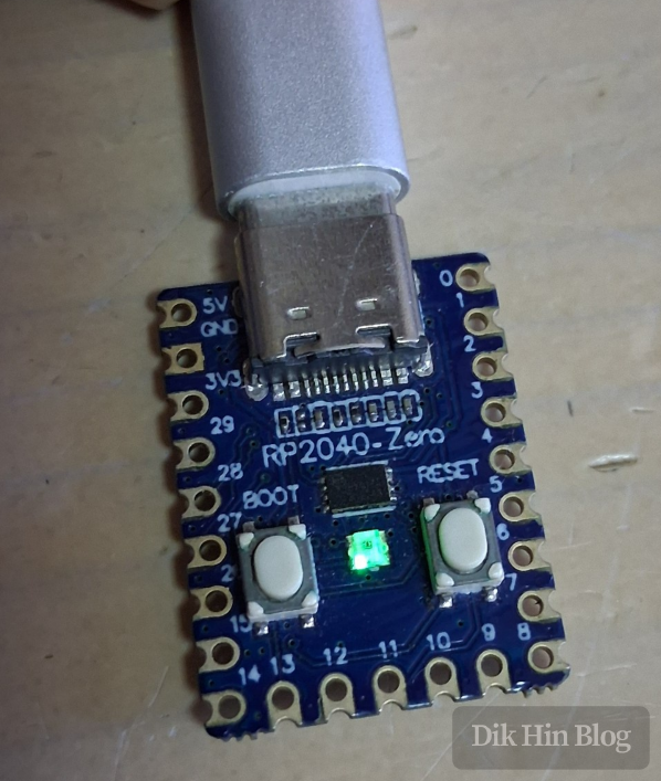
About the Development Board
There are two ways to program this development board. The first is using the official C++ SDK, I write my code and compile it into a binary using their toolchain, then upload it to the board. The second way is through MicroPython. If I don’t have strict performance requirements or need low-level access, MicroPython is simpler. It essentially wraps a translation layer and provides a Python 3 interface, while actually calling the official C++ SDK under the hood, kind of like an Arduino bootloader. Once I upload the MicroPython firmware to the board, I can interact with it via serial port.
Initial Overclocking Test
The RP2040 features dual-core ARM Cortex-M0+ processors with an official maximum frequency of 133MHz. I wanted to see how far I could push the overclocking. MicroPython has a machine.freq() function to adjust the frequency. In my simple tests, the board would freeze somewhere between 240MHz and 250MHz. Normally, to properly test overclocking, I need to run at high load for extended periods without issues to consider it stable. But here I’ll simplify things, if it responds after changing the frequency, I’ll call it OK, just to get a rough number.
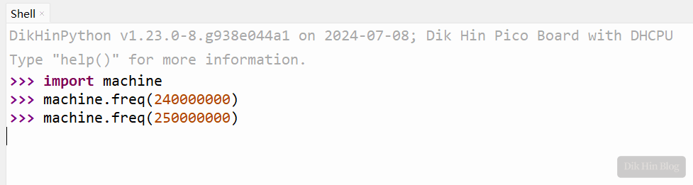
Initial testing shows this chip can reach about 240MHz.
Voltage Regulation Capability
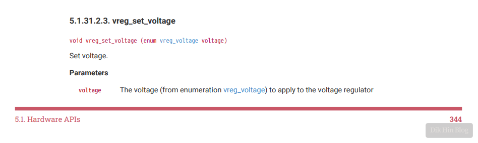
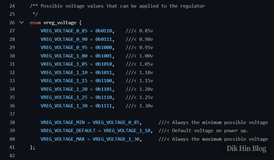
Looking through the official Pico SDK documentation, I found a vreg_set_voltage() function for adjusting voltage. Checking the corresponding enum, the adjustment range is from 0.85V to 1.3V, with a minimum step of 0.05V, and the default is 1.1V.
If I increase the voltage, the internal transistors can switch faster, theoretically making the core more stable at high frequencies and potentially achieving higher overclocks. Of course, increasing voltage has downsides, higher power consumption, more heat, and reduced lifespan. But I’m just experimenting out of curiosity, so I’ll ignore these drawbacks for now.
Modifying MicroPython
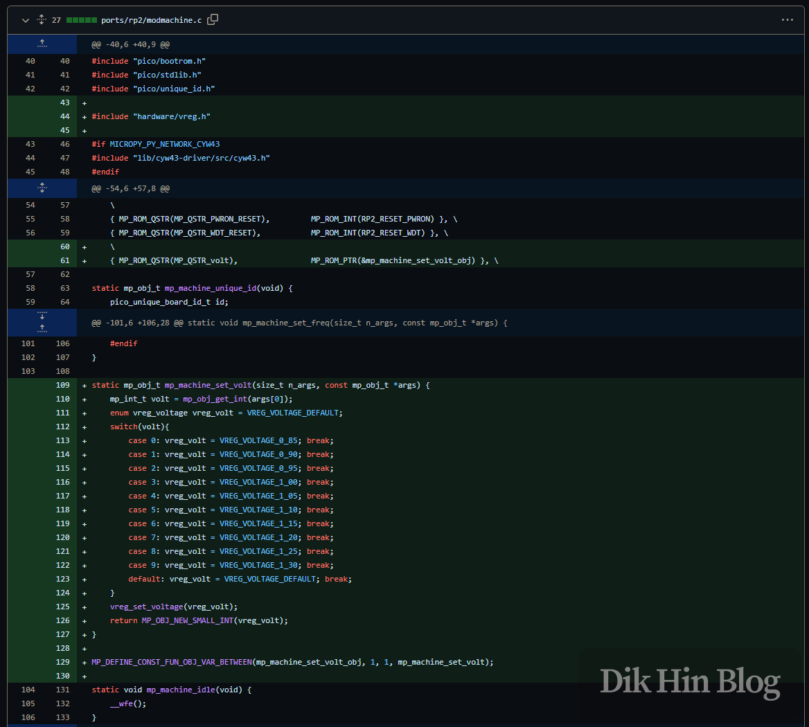
I discovered that MicroPython doesn’t natively support voltage adjustment, there’s no related function. So I modified MicroPython to add this capability. In the machine module, I first imported the vreg-related definitions from the official RP2040 SDK (line 44), then defined the new volt function (line 61). This function accepts one parameter for the voltage value (line 129), and finally implements the logic by calling the underlying vreg_set_voltage(). Here’s the code:
Adding USB Mass Storage
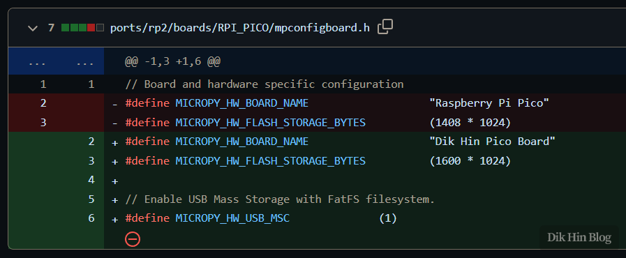
Additionally, the onboard Flash chip is a 25Q16 with 2MB capacity. After subtracting the compiled firmware size, there’s about 1.6MB left for user space to store Python code and data. MicroPython defaults to allocating 1.4MB, so I adjusted it to use all available space. I also defined MICROPY_HW_USB_MSC, which makes MicroPython emulate a FAT filesystem USB drive. This way, I can use my computer’s file explorer or phone’s file browser to manage the Flash user space directly, without needing to use an IDE like Thonny every time I want to update or upload codes.
Test Results
After compiling and uploading the firmware to the board, I started testing.
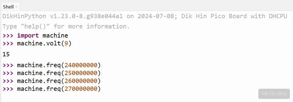
Using machine.volt() to set the voltage to the maximum 1.3V, the overclocking limit reached between 260MHz-270MHz.
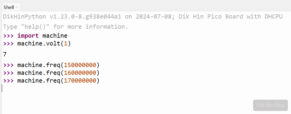
Conversely, setting a low voltage of 0.9V, the overclocking limit dropped to between 160MHz-170MHz (setting the minimum 0.85V caused an immediate crash).
So theoretically, for embedded devices, I could lower the voltage to save power and extend battery life. However, I only did rough testing here without actual stability runs. If I plan to use reduced voltage, I should thoroughly test stability to ensure it meets my requirements.
USB Drive Effect:
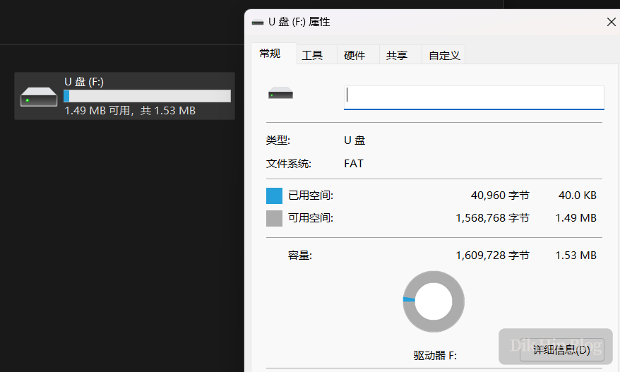
Done!